ESP32-LyraT V4.3スタートガイド
ESP32-LyraT V4.3 Getting Started Guide
このガイドでは、機能の説明、ESP32-LyraT V4.3オーディオ開発ボードの構成オプション、およびESP32-LyraTボードの使用を開始する方法について説明します。 このボードのバージョンが異なる場合は、セクション「LyraTの他のバージョン」を確認してください。
This guide provides users with functional descriptions, configuration options for ESP32-LyraT V4.3 audio development board, as well as how to get started with the ESP32-LyraT board. Check section Other Versions of LyraT, if you have different version of this board.
ESP32-LyraTは、デュアルコアESP32オーディオアプリケーション用に設計されたハードウェアプラットフォームです。たとえば、Wi-FiまたはBTオーディオスピーカー、音声ベースのリモートコントローラー、1つ以上のオーディオ機能を備えた接続されたスマート家電などです。
The ESP32-LyraT is a hardware platform designed for the dual-core ESP32 audio applications, e.g., Wi-Fi or BT audio speakers, speech-based remote controllers, connected smart-home appliances with one or more audio functionality, etc.
ESP32-LyraTはステレオオーディオボードです。 ローエンドアプリケーション向けのモノラルオーディオボードをお探しの場合は、ESP32-LyraT-Mini V1.2スタートガイドをご覧ください。
The ESP32-LyraT is a stereo audio board. If you are looking for a mono audio board, intended for lower end applications, check ESP32-LyraT-Mini V1.2 Getting Started Guide.
何が必要
What You Need
- 1 × ESP32 LyraT V4.3 ボード
1 × ESP32 LyraT V4.3 board
- 2 x デュポンのメスジャンパーワイヤー付き4オームスピーカーまたは3.5mmジャック付きヘッドフォン
2 x 4-ohm speakers with Dupont female jumper wires or headphones with a 3.5 mm jack
- 2 x Micro-USB 2.0ケーブル、タイプAからマイクロB
2 x Micro-USB 2.0 cables, Type A to Micro B
- 1× Windows、Linux、またはMacOSを搭載したPC
1 × PC loaded with Windows, Linux or Mac OS
今すぐこのボードの使用を開始したい場合は、「アプリケーション開発の開始」セクションに直接進んでください。
If you like to start using this board right now, go directly to section Start Application Development.
概要
Overview
ESP32-LyraT V4.3は、ESP32を中心に構築されたEspressifによって作成されたオーディオ開発ボードです。 これは、ESP32チップにすでに搭載されているものに加えて、オーディオ処理用のハードウェアと追加のRAMを提供することにより、オーディオアプリケーションを対象としています。 特定のハードウェアには次のものが含まれます:
The ESP32-LyraT V4.3 is an audio development board produced by Espressif built around ESP32. It is intended for audio applications, by providing hardware for audio processing and additional RAM on top of what is already onboard of the ESP32 chip. The specific hardware includes:
- ESP32-WROVERモジュール
ESP32-WROVER Module
- オーディオコーデックチップ
Audio Codec Chip
- 搭載されているデュアルマイク
Dual Microphones on board
- ヘッドホン入力
Headphone input
- 2 x 3ワットスピーカー出力
2 x 3-watt Speaker output
- デュアル補助入力
Dual Auxiliary Input
- MicroSDカードスロット(1回線または4回線)
MicroSD Card slot (1 line or 4 lines)
- 6つのボタン(2つの物理ボタンと4つのタッチボタン)
Six buttons (2 physical buttons and 4 touch buttons)
- JTAGヘッダー
JTAG header
- 統合されたUSB-UARTブリッジチップ
Integrated USB-UART Bridge Chip
- リチウムイオン電池-充電管理
Li-ion Battery-Charge Management
以下のブロック図は、ESP32-LyraTの主要コンポーネントとコンポーネント間の相互接続を示しています。
The block diagram below presents main components of the ESP32-LyraT and interconnections between components.
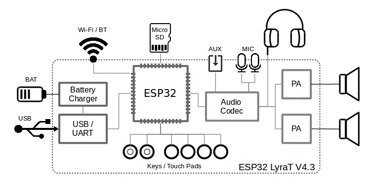
ESP32-LyraT Block Diagram
コンポーネント
Components
次のリストと図は、このガイドで使用されているESP32-LyraTの主要なコンポーネント、インターフェイス、およびコントロールについて説明しています。 これは、今必要なものだけをカバーしています。 このボードの詳細な技術文書については、ESP32-LyraT V4.3ハードウェアリファレンスおよびESP32-LyraT V4.3回路図(PDF)を参照してください。
The following list and figure describe key components, interfaces and controls of the ESP32-LyraT used in this guide. This covers just what is needed now. For detailed technical documentation of this board, please refer to ESP32-LyraT V4.3 Hardware Reference and ESP32 LyraT V4.3 schematic (PDF).
- ESP32-WROVERモジュール
ESP32-WROVER Module
- ESP32-WROVERモジュールにはESP32チップが含まれており、Wi-Fi / BT接続とデータ処理能力を提供するだけでなく、32 Mbit SPIフラッシュと32Mbit PSRAMを統合して柔軟なデータストレージを実現します。
The ESP32-WROVER module contains ESP32 chip to provide Wi-Fi / BT connectivity and data processing power as well as integrates 32 Mbit SPI flash and 32 Mbit PSRAM for flexible data storage.
- ヘッドフォン出力
Headphone Output
-
ヘッドホンを3.5mmステレオジャックに接続するための出力ソケット。
Output socket to connect headphones with a 3.5 mm stereo jack.
Note
ソケットは携帯電話のヘッドセットで使用でき、OMPT標準のヘッドセットとのみ互換性があります。 CTIAヘッドセットで動作します。 ウィキペディアのフォーンコネクタ(オーディオ)を参照してください。
The socket may be used with mobile phone headsets and is compatible with OMPT standard headsets only. It does work with CTIA headsets. Please refer to Phone connector (audio) on Wikipedia.
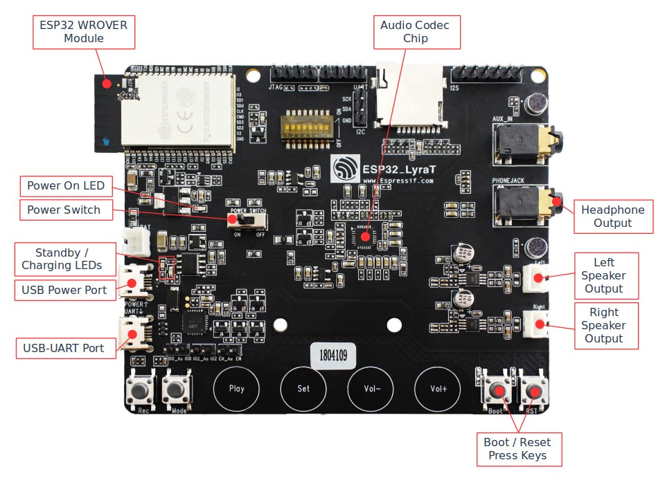
ESP32-LyraT V4.3 Board Layout Overview
- 左スピーカー出力
Left Speaker Output
- 4オームスピーカーを接続するための出力ソケット。 ピンのピッチは標準で2.54mm /0.1インチです。
Output socket to connect 4 ohm speaker. The pins have a standard 2.54 mm / 0.1” pitch.
- 右スピーカー出力
Right Speaker Output
- 4オームスピーカーを接続するための出力ソケット。 ピンのピッチは標準で2.54mm /0.1インチです。
Output socket to connect 4 ohm speaker. The pins have a standard 2.54 mm / 0.1” pitch.
- ブート/リセットプレスキー
Boot/Reset Press Keys
- 起動:起動ボタンを押したままリセットボタンを一瞬押すと、ファームウェアのアップロードモードが開始されます。 その後、ユーザーはシリアルポートを介してファームウェアをアップロードできます。 リセット:このボタンを押すだけでシステムがリセットされます。
Boot: holding down the Boot button and momentarily pressing the Reset button initiates the firmware upload mode. Then user can upload firmware through the serial port. Reset: pressing this button alone resets the system.
- オーディオコーデックチップ
Audio Codec Chip
- オーディオコーデックチップES8388は、ヘッドフォンアンプを備えた低電力ステレオオーディオコーデックです。 2チャンネルADC、2チャンネルDAC、マイクアンプ、ヘッドフォンアンプ、デジタルサウンドエフェクト、アナログミキシングおよびゲイン機能で構成されています。 I2SおよびI2Sバスを介してESP32-WROVERモジュールとインターフェイスし、オーディオアプリケーションとは独立してハードウェアでオーディオ処理を提供します。
The Audio Codec Chip, ES8388, is a low power stereo audio codec with a headphone amplifier. It consists of 2-channel ADC, 2-channel DAC, microphone amplifier, headphone amplifier, digital sound effects, analog mixing and gain functions. It is interfaced with ESP32-WROVER Module over I2S and I2S buses to provide audio processing in hardware independently from the audio application.
- USB-UARTポート
USB-UART Port
- PCとESP32-WROVERモジュール間の通信インターフェースとして機能します。
Functions as the communication interface between a PC and the ESP32 WROVER module.
- USB電源ポート
USB Power Port
- ボードに電源を供給します。
Provides the power supply for the board.
- スタンバイ/充電LED
Standby / Charging LEDs
- スタンバイの緑色のLEDは、マイクロUSBポートに電力が供給されていることを示します。 充電中の赤いLEDは、バッテリーソケットに接続されているバッテリーが充電中であることを示します。
The Standby green LED indicates that power has been applied to the Micro USB Port. The Charging red LED indicates that a battery connected to the Battery Socket is being charged.
- 電源スイッチ
Power Switch
- 電源オン/オフノブ:左に切り替えると、ボードの電源がオンになります。 右に切り替えると、ボードの電源がオフになります。
Power on/off knob: toggling it to the left powers the board on; toggling it to the right powers the board off.
- 電源オンLED
Power On LED
- 電源オンスイッチがオンになっていることを示す赤いLED。
Red LED indicating that Power On Switch is turned on.
アプリケーション開発を開始する
Start Application Development
ESP32-LyraTの電源を入れる前に、ボードが損傷の明らかな兆候がなく、良好な状態で受け取られていることを確認してください。
Before powering up the ESP32-LyraT, please make sure that the board has been received in good condition with no obvious signs of damage.
初期設定
Initial Setup
最初のサンプルアプリケーションをロードするためにボードを準備します:
Prepare the board for loading of the first sample application:
- 4オームのスピーカーを左右のスピーカー出力に接続します。 ヘッドホンをヘッドホン出力に接続することはオプションです。
Connect 4-ohm speakers to the Right and Left Speaker Output. Connecting headphones to the Headphone Output is an option.
- Micro-USBケーブルをPCとESP32-LyraTの両方のUSBポートに接続します。
Plug in the Micro-USB cables to the PC and to both USB ports of the ESP32 LyraT.
- スタンバイLED(緑色)が点灯するはずです。 バッテリーが接続されていない場合、充電LED(赤)が数秒ごとに点滅します。
The Standby LED (green) should turn on. Assuming that a battery is not connected, the Charging LED (red) will blink every couple of seconds.
- トグルは電源オンスイッチを離れました。
Toggle left the Power On Switch.
- 赤い電源オンLEDが点灯するはずです。
The red Power On LED should turn on.
これがLEDに表示されているものである場合、ボードはアプリケーションのアップロードの準備ができているはずです。 次に、次のセクションで説明する開発ツールをロードして構成することにより、PCを準備します。
If this is what you see on the LEDs, the board should be ready for application upload. Now prepare the PC by loading and configuring development tools what is discussed in the next section.
アプリケーションの開発
Develop Applications
ESP32-LyraTが最初にセットアップされてチェックされている場合は、開発ツールの準備を進めることができます。 「はじめに」セクションに移動します。このセクションでは、次の手順を説明します:
If the ESP32 LyraT is initially set up and checked, you can proceed with preparation of the development tools. Go to section Get Started, which will walk you through the following steps:
- C言語でESP32のアプリケーションを開発するための共通フレームワークを提供するPCにESP-IDFをセットアップします;
Set up ESP-IDF in your PC that provides a common framework to develop applications for the ESP32 in C language;
- ESP-ADFを入手して、オーディオアプリケーションに固有のAPIを用意します;
Get ESP-ADF to have the API specific for the audio applications;
- フレームワークにオーディオ固有のAPIを認識させるために、ESP-ADFへのパスを設定します;
Setup Path to ESP-ADF to make the framework aware of the audio specific API;
- ESP32-LyraTボードのサンプルオーディオアプリケーションを提供するプロジェクトを開始します;
Start a Project that will provide a sample audio application for the ESP32-LyraT board;
- 接続して構成し、アプリケーションをロードする準備をします;
Connect and Configure to prepare the application for loading;
- ビルド、フラッシュ、モニターこれにより、最終的にアプリケーションが実行され、音楽が再生されます;
Build, Flash and Monitor this will finally run the application and play some music.
LyraT V4.2からの主な変更点の概要
Summary of Key Changes from LyraT V4.2
- 赤色LEDインジケータライトを取り外しました。
Removed Red LED indicator light.
- ヘッドフォンジャックインサート検出を導入しました。
Introduced headphone jack insert detection.
- シングルパワーアンプ(PA)チップを2つの別々のチップに交換しました。
Replaced single Power Amplifier (PA) chip with two separate chips.
- バッテリー充電、ESP32、MicorSD、コーデックチップ、PAなどのいくつかの回路の電力管理設計を更新しました。
Updated power management design of several circuits: Battery Charging, ESP32, MicorSD, Codec Chip and PA.
- UART、コーデックチップ、左右のマイク、AUX入力、ヘッドフォン出力、MicroSD、プッシュボタン、自動アップロードなど、いくつかの回路の電気的実装設計を更新しました。
Updated electrical implementation design of several circuits: UART, Codec Chip, Left and Right Microphones, AUX Input, Headphone Output, MicroSD, Push Buttons and Automatic Upload.
LyraTの他のバージョン
Other Versions of LyraT
LyraTファミリーの他のボード
Other Boards from LyraT Family