ESP32-LyraT V4.2スタートガイド
ESP32-LyraT V4.2 Getting Started Guide
このガイドでは、機能の説明、ESP32-LyraT V4.2オーディオ開発ボードの構成オプション、およびESP32-LyraTボードの使用を開始する方法について説明します。
This guide provides users with functional descriptions, configuration options for ESP32-LyraT V4.2 audio development board, as well as how to get started with the ESP32-LyraT board.
ESP32-LyraT開発ボードは、デュアルコアESP32オーディオアプリケーション(Wi-FiまたはBTオーディオスピーカー、音声ベースのリモートコントローラー、オーディオ機能を備えたスマートホームアプライアンスなど)用に設計されたハードウェアプラットフォームです。
The ESP32-LyraT development board is a hardware platform designed for the dual-core ESP32 audio applications, e.g., Wi-Fi or BT audio speakers, speech-based remote controllers, smart-home appliances with audio functionality(ies), etc.
今すぐこのボードの使用を開始したい場合は、「アプリケーション開発の開始」セクションに直接進んでください。
If you like to start using this board right now, go directly to section Start Application Development.
何が必要
What You Need
- 1 × ESP32 LyraT V4.2ボード
1 × ESP32 LyraT V4.2 board
- 2 x デュポンのメスジャンパーワイヤー付き4オームスピーカーまたは3.5mmジャック付きヘッドフォン
2 x 4-ohm speakers with Dupont female jumper wires or headphones with a 3.5 mm jack
- 2 x Micro-USB 2.0ケーブル、タイプAからマイクロB
2 x Micro-USB 2.0 cables, Type A to Micro B
- 1 × Windows、Linux、またはMacOSを搭載したPC
1 × PC loaded with Windows, Linux or Mac OS
概要
Overview
ESP32-LyraT V4.2は、ESP32を中心に構築されたEspressifによって作成されたオーディオ開発ボードです。 これは、ESP32チップにすでに搭載されているものに加えて、オーディオ処理用のハードウェアと追加のRAMを提供することにより、オーディオアプリケーションを対象としています。 特定のハードウェアには次のものが含まれます:
The ESP32-LyraT V4.2 is an audio development board produced by Espressif built around ESP32. It is intended for audio applications, by providing hardware for audio processing and additional RAM on top of what is already onboard of the ESP32 chip. The specific hardware includes:
- ESP32-WROVERモジュール
ESP32-WROVER Module
- オーディオコーデックチップ
Audio Codec Chip
- 搭載されているデュアルマイク
Dual Microphones on board
- ヘッドホン入力
Headphone input
- 2 x 3ワットスピーカー出力
2 x 3-watt Speaker output
- デュアル補助入力
Dual Auxiliary Input
- MicroSDカードスロット (1ラインまたは4ライン)
MicroSD Card slot (1 line or 4 lines)
- 6つのボタン (2つの物理ボタンと4つのタッチボタン)
Six buttons (2 physical buttons and 4 touch buttons)
- JTAGヘッダ
JTAG header
- 統合されたUSB-UARTブリッジチップ
Integrated USB-UART Bridge Chip
- リチウムイオン電池-充電管理
Li-ion Battery-Charge Management
以下のブロック図は、ESP32-LyraTの主要コンポーネントとコンポーネント間の相互接続を示しています。
The block diagram below presents main components of the ESP32-LyraT and interconnections between components.
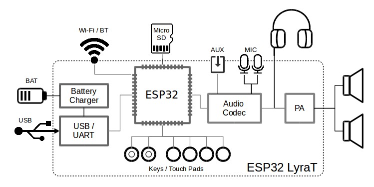
ESP32-LyraT Block Diagram
機能説明
Functional Description
次のリストと図は、ESP32-LyraTボードの主要なコンポーネント、インターフェイス、およびコントロールについて説明しています。
The following list and figure describe key components, interfaces and controls of the ESP32-LyraT board.
- ESP32-WROVERモジュール
ESP32-WROVER Module
- ESP32-WROVERモジュールにはESP32チップが含まれており、Wi-Fi / BT接続とデータ処理能力を提供するだけでなく、32Mbit SPIフラッシュと32Mbit PSRAMを統合して柔軟なデータストレージを実現します。
The ESP32-WROVER module contains ESP32 chip to provide Wi-Fi / BT connectivity and data processing power as well as integrates 32 Mbit SPI flash and 32 Mbit PSRAM for flexible data storage.
- 緑と赤のLED
Green and Red LEDs
- 専用APIを使用してオーディオアプリケーションの特定の動作状態を示すために、ESP32-WROVERモジュールによって制御される2つの汎用LED。
Two general purpose LEDs controlled by ESP32-WROVER Module to indicate certain operation states of the audio application using dedicated API.
- 機能ディップスイッチ
Function DIP Switch
- デバイス間、主にJTAGヘッダーとMicroSDカード間で共有されるGPIO12〜GPIO15ピンの機能を構成するために使用されます。 デフォルトでは、MicroSDカードはすべてのスイッチがオフの位置で有効になっています。 代わりにJTAGヘッダーを有効にするには、位置3、4、5、および6のスイッチをオンにする必要があります。 JTAGを使用せず、MicroSDカードを単線モードで動作させている場合は、GPIO12、GPIO13を他の機能に割り当てることができます。 詳細については、ESP32 LyraT V4.2の回路図を参照してください。
Used to configure function of GPIO12 to GPIO15 pins that are shared between devices, primarily between JTAG Header and MicroSD Card. By default, the MicroSD Card is enabled with all switches in OFF position. To enable the JTAG Header instead, switches in positions 3, 4, 5 and 6 should be put ON. If JTAG is not used and MicroSD Card is operated in the one-line mode, then GPIO12 and GPIO13 may be assigned to other functions. Please refer to ESP32 LyraT V4.2 schematic for more details.
- JTAGヘッダー
JTAG Header
- ESP32-WROVERモジュールのJTAGインターフェイスへのアクセスを提供します。 デバッグ、アプリケーションのアップロード、およびアプリケーションレベルのトレースなどの他のいくつかの機能の実装に使用できます。 ピン配置の詳細については、JTAGヘッダー / JP7を参照してください。 ヘッダーにJTAG信号を使用する前に、機能DIPスイッチを有効にする必要があります。 JTAGの動作中は、MicroSDカードを使用できず、一部のJTAG信号が両方のデバイスで共有されているため、切断する必要があることに注意してください。
Provides access to the JTAG interface of ESP32-WROVER Module. It may be used for debugging, application upload, as well as implementing several other functions, e.g., Application Level Tracing. See JTAG Header / JP7 for pinout details. Before using JTAG signals to the header, Function DIP Switch should be enabled. Please note that when JTAG is in operation, MicroSD Card cannot be used and should be disconnected because some of JTAG signals are shared by both devices.
- UARTヘッダー
UART Header
- シリアルポート:ESP32-WROVERモジュールとUSB-UARTブリッジチップ間のシリアルTX / RX信号へのアクセスを提供します。
Serial port: provides access to the serial TX/RX signals between ESP32-WROVER Module and USB-UART Bridge Chip.
- I2Cヘッダー
I2C Header
- I2Cインターフェースへのアクセスを提供します。 ESP32-WROVERモジュールとオーディオコーデックチップの両方がこのインターフェイスに接続されています。 ピン配列の詳細については、I2Cヘッダー / JP5を参照してください。
Provides access to the I2C interface. Both ESP32-WROVER Module and Audio Codec Chip are connected to this interface. See I2C Header / JP5 for pinout details.
- MicroSDカード
MicroSD Card
- 開発ボードは、SPI / 1ビット/ 4ビットモードのMicroSDカードをサポートし、MicroSDカードにオーディオファイルを保存または再生できます。 ピン配置の詳細については、MicroSDカード / J5を参照してください。 一部の信号は両方のデバイスで共有されているため、JTAGは使用できず、MicroSDカードの動作中に機能DIPスイッチを設定して切断する必要があることに注意してください。
The development board supports a MicroSD card in SPI/1-bit/4-bit modes, and can store or play audio files in the MicroSD card. See MicroSD Card / J5 for pinout details. Note that JTAG cannot be used and should be disconnected by setting Function DIP Switch when MicroSD Card is in operation, because some of signals are shared by both devices.
- I2Sヘッダ
I2S Header
- I2Sインターフェースへのアクセスを提供します。 ESP32-WROVERモジュールとオーディオコーデックチップの両方がこのインターフェイスに接続されています。 ピン配列の詳細については、I2Sヘッダー / JP4を参照してください。
Provides access to the I2S interface. Both ESP32-WROVER Module and Audio Codec Chip are connected to this interface. See I2S Header / JP4 for pinout details.
- 左マイク
Left Microphone
- オーディオコーデックチップのIN1に接続されたオンボードマイク。
Onboard microphone connected to IN1 of the Audio Codec Chip.
- AUX入力
AUX Input
- オーディオコーデックチップのIN2(左右のチャンネル)に接続された補助入力ソケット。 3.5mmステレオジャックを使用してこのソケットに接続します。
Auxiliary input socket connected to IN2 (left and right channel) of the Audio Codec Chip. Use a 3.5 mm stereo jack to connect to this socket.
- ヘッドフォン出力
Headphone Output
- ヘッドホンを3.5mmステレオジャックに接続するための出力ソケット。
Output socket to connect headphones with a 3.5 mm stereo jack.
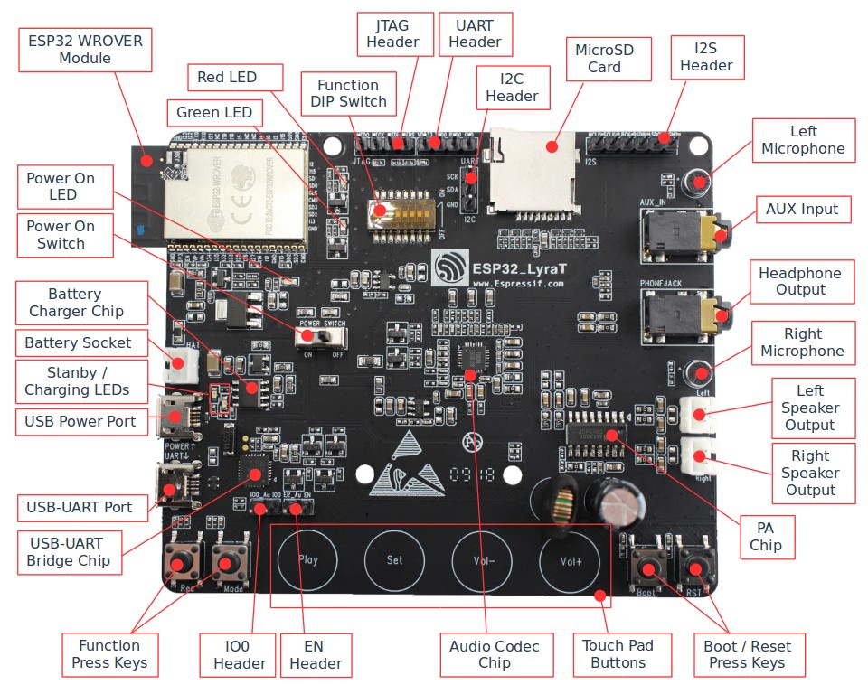
ESP32-LyraT V4.2 Board Layout
- 右のマイク
Right Microphone
- オーディオコーデックチップのIN1に接続されたオンボードマイク。
Onboard microphone connected to IN1 of the Audio Codec Chip.
- 左スピーカー出力
Left Speaker Output
- 4オームスピーカーを接続するための出力ソケット。 ピンのピッチは標準で2.54mm /0.1インチです。
Output socket to connect 4 ohm speaker. The pins have a standard 2.54 mm / 0.1” pitch.
- 右スピーカー出力
Right Speaker Output
- 4オームスピーカーを接続するための出力ソケット。 ピンのピッチは標準で2.54mm /0.1インチです。
Output socket to connect 4 ohm speaker. The pins have a standard 2.54 mm / 0.1” pitch.
- PAチップ
PA Chip
- 2つの4オームスピーカーを駆動するためのオーディオコーデックチップからのステレオオーディオ信号を増幅するために使用されるパワーアンプ。
A power amplifier used to amplify stereo audio signal from the Audio Codec Chip for driving two 4-ohm speakers.
- ブート/リセットプレスキー
Boot/Reset Press Keys
- 起動:起動ボタンを押したままリセットボタンを一瞬押すと、ファームウェアのアップロードモードが開始されます。 その後、ユーザーはシリアルポートを介してファームウェアをアップロードできます。 リセット:このボタンを押すだけでシステムがリセットされます。
Boot: holding down the Boot button and momentarily pressing the Reset button initiates the firmware upload mode. Then user can upload firmware through the serial port. Reset: pressing this button alone resets the system.
- タッチパッドボタン
Touch Pad Buttons
- Play、Sel、Vol+、Vol-のラベルが付いた4つのタッチパッド。 これらはESP32-WROVERモジュールにルーティングされ、専用APIを使用したオーディオアプリケーションのUIの開発とテストを目的としています。
Four touch pads labeled Play, Sel, Vol+ and Vol-. They are routed to ESP32-WROVER Module and intended for development and testing of a UI for audio applications using dedicated API.
- オーディオコーデックチップ
Audio Codec Chip
- オーディオコーデックチップES8388は、ヘッドフォンアンプを備えた低電力ステレオオーディオコーデックです。 2チャンネルADC、2チャンネルDAC、マイクアンプ、ヘッドフォンアンプ、デジタルサウンドエフェクト、アナログミキシングおよびゲイン機能で構成されています。 I2SおよびI2Sバスを介してESP32-WROVERモジュールとインターフェイスし、オーディオアプリケーションとは独立してハードウェアでオーディオ処理を提供します。
The Audio Codec Chip, ES8388, is a low power stereo audio codec with a headphone amplifier. It consists of 2-channel ADC, 2-channel DAC, microphone amplifier, headphone amplifier, digital sound effects, analog mixing and gain functions. It is interfaced with ESP32-WROVER Module over I2S and I2S buses to provide audio processing in hardware independently from the audio application.
- ENヘッダー
EN Header
- このヘッダーにジャンパーをインストールして、ESP32へのアプリケーションの自動ロードを有効にします。 IO0ヘッダーとENヘッダーの両方にジャンパーを一緒に取り付けたり取り外したりします。
Install a jumper on this header to enable automatic loading of application to the ESP32. Install or remove jumpers together on both IO0 and EN headers.
- IO0ヘッダー
IO0 Header
- このヘッダーにジャンパーをインストールして、ESP32へのアプリケーションの自動ロードを有効にします。 IO0ヘッダーとENヘッダーの両方にジャンパーを一緒に取り付けたり取り外したりします。
Install a jumper on this header to enable automatic loading of application to the ESP32. Install or remove jumpers together on both IO0 and EN headers.
- 機能プレスキー
Function Press Keys
- RecとModeというラベルの付いた2つのキー。 これらはESP32-WROVERモジュールにルーティングされ、専用APIを使用してオーディオアプリケーションのUIを開発およびテストすることを目的としています。
Two key labeled Rec and Mode. They are routed to ESP32-WROVER Module and intended for developing and testing a UI for audio applications using dedicated API.
- USB-UARTブリッジチップ
USB-UART Bridge Chip
- シングルチップUSB-UARTブリッジは、最大1Mbpsの転送速度を提供します。
A single chip USB-UART bridge provides up to 1 Mbps transfers rate.
- USB-UARTポート
USB-UART Port
- PCとESP32モジュール間の通信インターフェースとして機能します。
Functions as the communication interface between a PC and the ESP32 module.
- USB電源ポート
USB Power Port
- ボードに電源を供給します。
Provides the power supply for the board.
- スタンバイ/充電LED
Standby / Charging LEDs
- スタンバイの緑色のLEDは、マイクロUSBポートに電力が供給されていることを示します。 充電中の赤いLEDは、バッテリーソケットに接続されているバッテリーが充電中であることを示します。
The Standby green LED indicates that power has been applied to the Micro USB Port. The Charging red LED indicates that a battery connected to the Battery Socket is being charged.
- バッテリー充電器チップ
Battery Charger Chip
- 定電流& 単セルリチウムイオン電池AP5056用定電圧リニア充電器。 マイクロUSBポートを介してバッテリーソケットに接続されたバッテリーの充電に使用されます。
Constant current & constant voltage linear charger for single cell lithium-ion batteries AP5056. Used for charging of a battery connected to the Battery Socket over the Micro USB Port.
- 電源オンスイッチ
Power On Switch
- 電源オン/オフノブ:左に切り替えると、ボードの電源がオンになります。 右に切り替えると、ボードの電源がオフになります。
Power on/off knob: toggling it to the left powers the board on; toggling it to the right powers the board off.
- バッテリーソケット
Battery Socket
- シングルセルリチウムイオンバッテリーを接続するための2ピンソケット。
Two pins socket to connect a single cell Li-ion battery.
- 電源オンLED
Power On LED
電源オンスイッチがオンになっていることを示す赤いLED。
Red LED indicating that Power On Switch is turned on.
Note
電源オンスイッチは、リチウムイオンバッテリーの充電に影響を与えたり切断したりしません。
The Power On Switch does not affect / disconnect the Li-ion battery charging.
ハードウェアセットアップオプション
Hardware Setup Options
ESP32-LyraTボードのハードウェア構成を変更するには、いくつかのオプションがあります。 オプションは、機能DIPスイッチで選択できます。
There are a couple of options to change the hardware configuration of the ESP32-LyraT board. The options are selectable with the Function DIP Switch.
1線式モードでMicroSDカードを有効にする
Enable MicroSD Card in 1-wire Mode
ディップスイッチ
DIP SW |
ポジション
Position |
|---|---|
| 1 | OFF |
| 2 | OFF |
| 3 | OFF |
| 4 | OFF |
| 5 | OFF |
| 6 | OFF |
| 7 | OFF 1 |
| 8 | n/a |
- AUX入力検出は、DIP SW7をオンに切り替えることで有効にできます。
AUX Input detection may be enabled by toggling the DIP SW 7 ON
このモードの場合:
In this mode:
- JTAG機能は利用できません
JTAG functionality is not available
- Vol-タッチボタンはAPIで使用できます
Vol- touch button is available for use with the API
4線式モードでMicroSDカードを有効にする
Enable MicroSD Card in 4-wire Mode
ディップスイッチ
DIP SW |
ポジション
Position |
|---|---|
| 1 | ON |
| 2 | ON |
| 3 | OFF |
| 4 | OFF |
| 5 | OFF |
| 6 | OFF |
| 7 | OFF |
| 8 | n/a |
このモードの場合:
In this mode:
- JTAG機能は利用できません
JTAG functionality is not available
- Vol-タッチボタンはAPIで使用できません
Vol- touch button is not available for use with the API
- APIからのAUX入力の検出は利用できません
AUX Input detection from the API is not available
JTAGを有効にする
Enable JTAG
ディップスイッチ
DIP SW |
ポジション
Position |
|---|---|
| 1 | OFF |
| 2 | OFF |
| 3 | ON |
| 4 | ON |
| 5 | ON |
| 6 | ON |
| 7 | ON |
| 8 | n/a |
このモードの場合:
In this mode:
- MicroSDカード機能は利用できません。スロットからカードを取り外してください
MicroSD Card functionality is not available, remove the card from the slot
- Vol-タッチボタンはAPIで使用できません
Vol- touch button is not available for use with the API
- APIからのAUX入力の検出は利用できません
AUX Input detection from the API is not available
ESP32ピンの割り当て
Allocation of ESP32 Pins
ESP32モジュールのいくつかのピン/端子がオンボードハードウェアに割り当てられています。 GPIO0やGPIO2のように、それらのいくつかは複数の機能を持っています。 具体的な詳細については、以下の表またはESP32 LyraT V4.2の回路図を参照してください。
Several pins / terminals of ESP32 modules are allocated to the on board hardware. Some of them, like GPIO0 or GPIO2, have multiple functions. Please refer to the tables below or ESP32 LyraT V4.2 schematic for specific details.
赤/緑のLED
Red / Green LEDs
ESP32ピン
ESP32 Pin |
LEDの色
LED Color |
|
|---|---|---|
| 1 | GPIO19 | 赤色LED
Red LED |
| 2 | GPIO22 | 緑色のLED
Green LED |
タッチパッド
Touch Pads
ESP32ピン
ESP32 Pin |
タッチパッド機能
Touch Pad Function |
|
|---|---|---|
| 1 | GPIO33 | Play |
| 2 | GPIO32 | Set |
| 3 | GPIO13 | Vol- 1 |
| 4 | GPIO27 | Vol+ |
- JTAGを使用している場合、Vol-機能は使用できません。 また、4線式モードで動作するように構成されたMicroSDカードでは使用できません。
Vol- function is not available if JTAG is used. It is also not available for the MicroSD Card configured to operate in 4-wire mode.
MicroSDカード/ J5
MicroSD Card / J5
ESP32ピン
ESP32 Pin |
MicroSD信号
MicroSD Signal |
|
|---|---|---|
| 1 | MTDI / GPIO12 | DATA2 |
| 2 | MTCK / GPIO13 | CD / DATA3 |
| 3 | MTDO / GPIO15 | CMD |
| 4 | MTMS / GPIO14 | CLK |
| 5 | GPIO2 | DATA0 |
| 6 | GPIO4 | DATA1 |
| 7 | GPIO21 | CD |
ENおよびIO0ヘッダー/ JP23およびJP24
EN and IO0 Headers / JP23 and J24
ESP32ピン
ESP32 Pin |
ヘッダーピン
Header Pin |
|
|---|---|---|
| 1 | n/a | EN_Auto |
| 2 | EN | EN |
ESP32ピン
ESP32 Pin |
ヘッダーピン
Header Pin |
|
|---|---|---|
| 1 | n/a | IO0_Auto |
| 2 | GPIO0 | IO0 |
I2Sヘッダー/ JP4
I2S Header / JP4
I2Sヘッダーピン
I2C Header Pin |
ESP32ピン
ESP32 Pin |
|
|---|---|---|
| 1 | MCLK | GPI0 |
| 2 | SCLK | GPIO5 |
| 1 | LRCK | GPIO25 |
| 2 | DSDIN | GPIO26 |
| 3 | ASDOUT | GPIO35 |
| 3 | GND | GND |
I2Cヘッダー/ JP5
I2C Header / JP5
I2Cヘッダーピン
I2C Header Pin |
ESP32ピン
ESP32 Pin |
|
|---|---|---|
| 1 | SCL | GPIO23 |
| 2 | SDA | GPIO18 |
| 3 | GND | GND |
JTAGヘッダー/ JP7
JTAG Header / JP7
ESP32ピン
ESP32 Pin |
JTAG信号
JTAG Signal |
|
|---|---|---|
| 1 | MTDO / GPIO15 | TDO |
| 2 | MTCK / GPIO13 | TCK |
| 3 | MTDI / GPIO12 | TDI |
| 4 | MTMS / GPIO14 | TMS |
機能ディップスイッチ/ JP8
Function DIP Switch / JP8
スイッチをオフにします
Switch OFF |
スイッチをつける
Switch ON |
|
|---|---|---|
| 1 | GPIO12が割り当てられていません
GPIO12 not allocated |
MicroSDカード4線
MicroSD Card 4-wire |
| 2 | タッチVol-を有効にする
Touch Vol- enabled |
MicroSDカード4線
MicroSD Card 4-wire |
| 3 | MicroSDカード
MicroSD Card |
JTAG
JTAG |
| 4 | MicroSDカード
MicroSD Card |
JTAG
JTAG |
| 5 | MicroSDカード
MicroSD Card |
JTAG
JTAG |
| 6 | MicroSDカード
MicroSD Card |
JTAG
JTAG |
| 7 | MicroSDカード4線
MicroSD Card 4-wire |
AUXIN検出1
AUX IN detect 1 |
| 8 | 使用されていない
not used |
使用されていない
not used |
- システムの電源投入時に、AUX入力信号ピンを接続しないでください。 そうしないと、ESP32が正しく起動できない場合があります。
The AUX Input signal pin should not be be plugged in when the system powers up. Otherwise the ESP32 may not be able to boot correctly.
アプリケーション開発を開始する
Start Application Development
ESP32-LyraTの電源を入れる前に、ボードが損傷の明らかな兆候がなく、良好な状態で受け取られていることを確認してください。
Before powering up the ESP32-LyraT, please make sure that the board has been received in good condition with no obvious signs of damage.
初期設定
Initial Setup
最初のサンプルアプリケーションをロードするためにボードを準備します:
Prepare the board for loading of the first sample application:
- IO0およびENヘッダーにジャンパーをインストールして、アプリケーションの自動アップロードを有効にします。 ジャンパーがない場合は、ブート/RSTボタンを使用してアップロードをトリガーできます。
Install jumpers on IO0 and EN headers to enable automatic application upload. If there are no jumpers then upload may be triggered using Boot / RST buttons.
- 4オームのスピーカーを左右のスピーカー出力に接続します。ヘッドフォンをヘッドフォン出力に接続することはオプションです。
Connect 4-ohm speakers to the Right and Left Speaker Output.Connecting headphones to the Headphone Output is an option.
- Micro-USBケーブルをPCとESP32LyraTの両方のUSBポートに接続します。
Plug in the Micro-USB cables to the PC and to both USB ports of the ESP32 LyraT.
- スタンバイLED(緑色)が点灯するはずです。 バッテリーが接続されていない場合、充電LEDは数秒ごとに点滅します。
The Standby LED (green) should turn on. Assuming that a battery is not connected, the Charging LED will blink every couple of seconds.
- トグルは電源オンスイッチを離れました。
Toggle left the Power On Switch.
- 赤い電源オンLEDが点灯するはずです。
The red Power On LED should turn on.
これがLEDに表示されているものである場合、ボードはアプリケーションのアップロードの準備ができているはずです。 次に、次のセクションで説明する開発ツールをロードして構成することにより、PCを準備します。
If this is what you see on the LEDs, the board should be ready for application upload. Now prepare the PC by loading and configuring development tools what is discussed in the next section.
アプリケーションの開発
Develop Applications
ESP32 LyraTが最初にセットアップされてチェックされている場合は、開発ツールの準備を進めることができます。 「はじめに」セクションに移動します。このセクションでは、次の手順を説明します:
If the ESP32 LyraT is initially set up and checked, you can proceed with preparation of the development tools. Go to section Get Started, which will walk you through the following steps:
- C言語でESP32のアプリケーションを開発するための共通フレームワークを提供するESP-IDFをPCにセットアップします。
Set up ESP-IDF in your PC that provides a common framework to develop applications for the ESP32 in C language;
- ESP-ADFを入手して、オーディオアプリケーションに固有のAPIを用意します;
Get ESP-ADF to have the API specific for the audio applications;
- フレームワークにオーディオ固有のAPIを認識させるために、ESP-ADFへのパスを設定します;
Setup Path to ESP-ADF to make the framework aware of the audio specific API;
- ESP32-LyraTボードのサンプルオーディオアプリケーションを提供するプロジェクトを開始します;
Start a Project that will provide a sample audio application for the ESP32-LyraT board;
- 接続して構成し、アプリケーションをロードする準備をします;
Connect and Configure to prepare the application for loading;
- ビルド、フラッシュ、モニターこれにより、最終的にアプリケーションが実行され、音楽が再生されます。
Build, Flash and Monitor this will finally run the application and play some music.