ESP32-LyraTD-MSC V2.2スタートガイド
ESP32-LyraTD-MSC V2.2 Getting Started Guide
このガイドでは、機能の説明、ESP32-LyraTD-MSC V2.2オーディオ開発ボードの構成オプション、およびESP32-LyraTD-MSCボードの使用を開始する方法について説明します。
This guide provides users with functional descriptions, configuration options for ESP32-LyraTD-MSC V2.2 audio development board, as well as how to get started with the ESP32-LyraTD-MSC board.
ESP32-LyraTD-MSCは、スマートスピーカーとAIアプリケーション向けに設計されたハードウェアプラットフォームです。 これは、音響エコーキャンセレーション(AEC)、自動音声認識(ASR)、ウェイクアップ割り込み、および音声対話をサポートします。
The ESP32-LyraTD-MSC is a hardware platform designed for smart speakers and AI applications. It supports Acoustic Echo Cancellation (AEC), Automatic Speech Recognition (ASR), Wake-up Interrupt and Voice Interaction.
何が必要
What You Need
- 1 × ESP32-LyraTD-MSC V2.2ボード
1 × ESP32-LyraTD-MSC V2.2 board
- 2 x デュポンのメスジャンパーワイヤー付き4オームスピーカーまたは3.5mmジャック付きヘッドフォン
2 x 4-ohm speakers with Dupont female jumper wires or headphones with a 3.5 mm jack
- 2 x Micro-USB 2.0ケーブル、タイプAからマイクロB
2 x Micro-USB 2.0 cables, Type A to Micro B
- 1 × Windows、Linux、またはMacOSを搭載したPC
1 × PC loaded with Windows, Linux or Mac OS
今すぐこのボードの使用を開始したい場合は、「アプリケーション開発の開始」セクションに直接進んでください。
If you like to start using this board right now, go directly to section Start Application Development.
概要
Overview
ESP32-LyraTD-MSC V2.2は、ESP32を中心に構築されたEspressifによって作成されたオーディオ開発ボードです。 これは、ESP32チップにすでに搭載されているものに加えて、デジタル信号処理用のハードウェア、マイクアレイ、および追加のRAMを提供することにより、スマートスピーカーおよびAIアプリケーションを対象としています。
The ESP32-LyraTD-MSC V2.2 is an audio development board produced by Espressif built around ESP32. It is intended for smart speakers and AI applications, by providing hardware for digital signal processing, microphone array and additional RAM on top of what is already onboard of the ESP32 chip.
このオーディオ開発ボードは、2つの部分で構成されています。3つのマイクアレイ、ファンクションキー、およびLEDライトを提供する上部ボード(B)。 下部ボード(A)は、ESP32-WROVER-B、MicroSemiデジタル信号処理(DSP)チップ、および電力管理モジュールを統合しています。
This audio development board consists of two parts: the upper board (B), which provides a three-microphone array, function keys and LED lights; and the lower board (A), which integrates ESP32-WROVER-B, a MicroSemi Digital Signal Processing (DSP) chip, and a power management module.
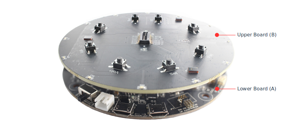
ESP32-LyraTD-MSC Side View
特定のハードウェアには次のものが含まれます:
The specific hardware includes:
- ESP32-WROVER-Bモジュール
ESP32-WROVER-B Module
- DSP (デジタル信号処理) チップ
DSP (Digital Signal Processing) chip
- 遠距離音声ピックアップをサポートする3つのデジタルマイク
Three digital Microphones that support far-field voice pick-up
- 2 x 3ワットスピーカー出力
2 x 3-watt Speaker output
- ヘッドホン出力
Headphone output
- MicroSDカードスロット (1回線または4回線)
MicroSD Card slot (1 line or 4 lines)
- ボードの端に円形に配置された個別に制御された12個のLED
Individually controlled Twelve LEDs distributed in a circle on the board’s edge
- ユーザー機能を割り当てることができる6つの機能ボタン
Six Function Buttons that may be assigned user functions
- いくつかのインターフェースポート:I2S、I2C、SPI、JTAG
Several interface ports: I2S, I2C, SPI and JTAG
- 統合されたUSB-UARTブリッジチップ
Integrated USB-UART Bridge Chip
- リチウムイオン電池-充電管理
Li-ion Battery-Charge Management
以下のブロック図は、ESP32-LyraTD-MSCの主要コンポーネントとコンポーネント間の相互接続を示しています。
The block diagram below presents main components of the ESP32-LyraTD-MSC and interconnections between components.
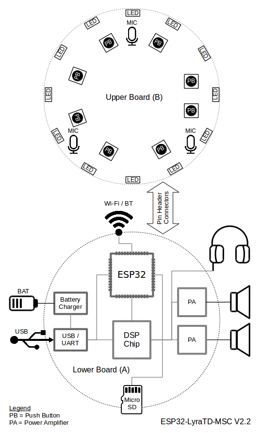
ESP32-LyraTD-MSC Block Diagram
コンポーネント
Components
次のリストと図は、このガイドで使用されているESP32-LyraTD-MSCの主要なコンポーネント、インターフェイス、およびコントロールについて説明しています。 これは、今必要なものだけをカバーしています。 詳細については、関連ドキュメントに記載されている回路図を参照してください。
The following list and figure describe key components, interfaces and controls of the ESP32-LyraTD-MSC used in this guide. This covers just what is needed now. For additional details please refer to schematics provided in Related Documents.
- ESP32-WROVER-Bモジュール
ESP32-WROVER-B Module
- ESP32-WROVER-Bモジュールには、Wi-Fi / BT接続とデータ処理能力を提供するESP32チップが含まれているほか、32 Mbit SPIフラッシュと64 Mbit PSRAMを統合して柔軟なデータストレージを実現します。
The ESP32-WROVER-B module contains ESP32 chip to provide Wi-Fi / BT connectivity and data processing power as well as integrates 32 Mbit SPI flash and 64 Mbit PSRAM for flexible data storage.
- DSPチップ
DSP Chip
- デジタル信号処理チップZL38063は、自動音声認識(ASR)アプリケーションに使用されます。 外部マイクアレイからオーディオデータをキャプチャし、Digital-to-Analog-Converter(DAC)ポートを介してオーディオ信号を出力します。
The Digital Signal Processing chip ZL38063 is used for Automatic Speech Recognition (ASR) applications. It captures audio data from an external microphone array and outputs audio signals through its Digital-to-Analog-Converter (DAC) port.
- ヘッドフォン出力
Headphone Output
ヘッドホンを3.5mmステレオジャックに接続するための出力ソケット。
Output socket to connect headphones with a 3.5 mm stereo jack.
Note
ソケットは携帯電話のヘッドセットで使用でき、OMPT標準のヘッドセットとのみ互換性があります。 CTIAヘッドセットで動作します。 ウィキペディアのフォーンコネクタ(オーディオ)を参照してください。
The socket may be used with mobile phone headsets and is compatible with OMPT standard headsets only. It does work with CTIA headsets. Please refer to Phone connector (audio) on Wikipedia.
- 左スピーカー出力
Left Speaker Output
- 4オームスピーカーを接続するための出力ソケット。 ピンのピッチは標準で2.54mm /0.1インチです。
Output socket to connect 4 ohm speaker. The pins have a standard 2.54 mm / 0.1” pitch.
- 右スピーカー出力
Right Speaker Output
- 4オームスピーカーを接続するための出力ソケット。 ピンのピッチは標準で2.54mm /0.1インチです。
Output socket to connect 4 ohm speaker. The pins have a standard 2.54 mm / 0.1” pitch.
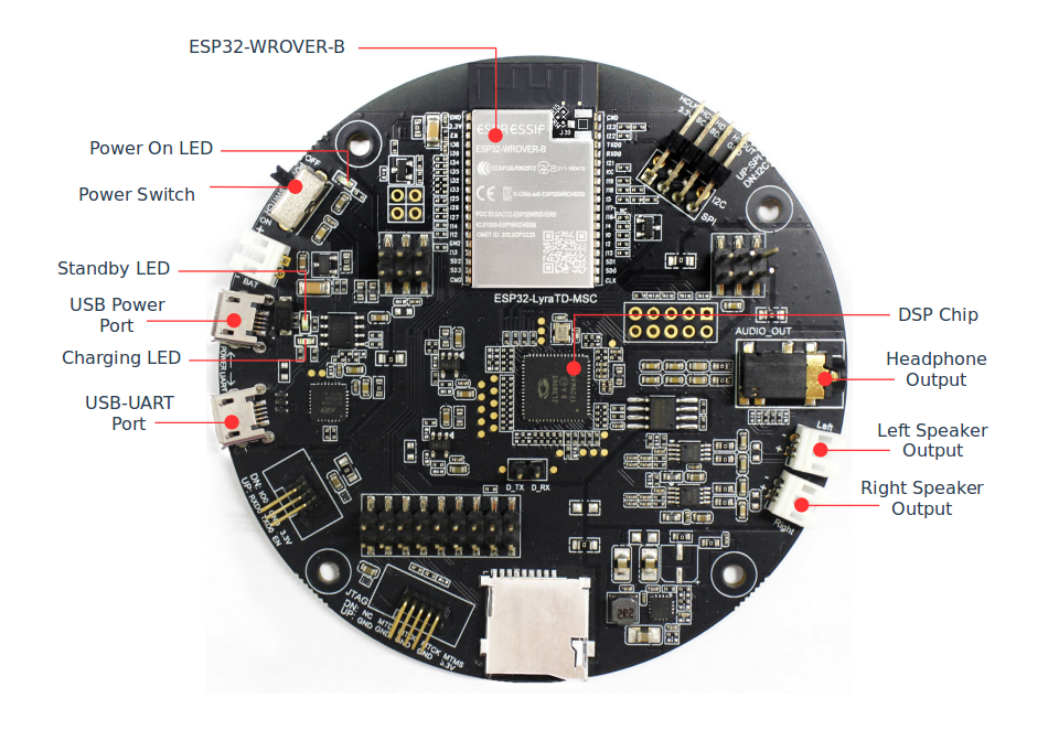
ESP32-LyraTD-MSC V2.2 Lower Board (A) Components
- USB-UARTポート
USB-UART Port
- PCとESP32-WROVERモジュール間の通信インターフェースとして機能します。
Functions as the communication interface between a PC and the ESP32 WROVER module.
- USB電源ポート
USB Power Port
- ボードに電源を供給します。
Provides the power supply for the board.
- スタンバイ/充電LED
Standby / Charging LEDs
- スタンバイの緑色のLEDは、マイクロUSBポートに電力が供給されていることを示します。 充電中の赤いLEDは、バッテリーソケットに接続されているバッテリーが充電中であることを示します。
The Standby green LED indicates that power has been applied to the Micro USB Port. The Charging red LED indicates that a battery connected to the Battery Socket is being charged.
- 電源スイッチ
Power Switch
- 電源オン/オフノブ:右に切り替えると、ボードの電源がオンになります。 それ以外の場合は、ボードの電源をオフにします。
Power on/off knob: toggling it right powers the board on; otherwise powers the board off.
- 電源オンLED
Power On LED
- 電源スイッチがオンになっていることを示す赤いLED。
Red LED indicating that Power Switch is turned on.
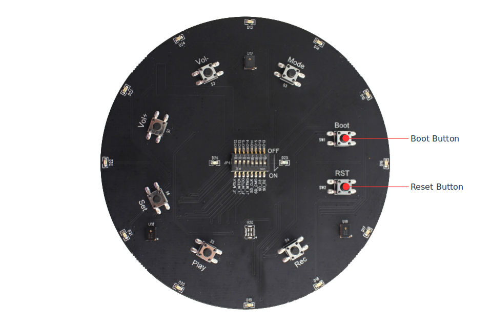
ESP32-LyraTD-MSC V2.2 Upper Board (B) Components
- ブート/リセットボタン
Boot/Reset Buttons
起動:起動ボタンを押したままリセットボタンを一瞬押すと、ファームウェアのアップロードモードが開始されます。 その後、ユーザーはシリアルポートを介してファームウェアをアップロードできます。
Boot: holding down the Boot button and momentarily pressing the Reset button initiates the firmware upload mode. Then user can upload firmware through the serial port.
リセット:このボタンを押すだけでシステムがリセットされます。
Reset: pressing this button alone resets the system.
アプリケーション開発を開始する
Start Application Development
ESP32-LyraTD-MSCの電源を入れる前に、ボードが損傷の明らかな兆候がなく、良好な状態で受け取られていることを確認してください。 ESP32-LyraTD-MSCの下部Aボードと上部Bボードの両方をしっかりと接続する必要があります。
Before powering up the ESP32-LyraTD-MSC, please make sure that the board has been received in good condition with no obvious signs of damage. Both the lower A and the upper B board of the ESP32-LyraTD-MSC should be firmly connected together.
初期設定
Initial Setup
最初のサンプルアプリケーションをロードするためにボードを準備します:
Prepare the board for loading of the first sample application:
- 4オームのスピーカーを左右のスピーカー出力に接続します。 ヘッドホンをヘッドホン出力に接続することはオプションです。
Connect 4-ohm speakers to the Right and Left Speaker Output. Connecting headphones to the Headphone Output is an option.
- Micro-USBケーブルをPCとESP32-LyraTD-MSCの両方のUSBポートに接続します。
Plug in the Micro-USB cables to the PC and to both USB ports of the ESP32-LyraTD-MSC.
- スタンバイLED(緑色)が点灯するはずです。 バッテリーが接続されていない場合、充電LED(赤)が数秒ごとに点滅します。
The Standby LED (green) should turn on. Assuming that a battery is not connected, the Charging LED (red) will blink every couple of seconds.
- 電源スイッチを右に切り替えます。
Toggle right the Power Switch.
- 赤い電源オンLEDが点灯するはずです。
The red Power On LED should turn on.
これがLEDに表示されているものである場合、ボードはアプリケーションのアップロードの準備ができているはずです。 次に、次のセクションで説明する開発ツールをロードして構成することにより、PCを準備します。
If this is what you see on the LEDs, the board should be ready for application upload. Now prepare the PC by loading and configuring development tools what is discussed in the next section.
アプリケーションの開発
Develop Applications
ESP32-LyraTD-MSCが最初にセットアップされ、チェックされている場合は、開発ツールの準備を進めることができます。 「はじめに」セクションに移動します。このセクションでは、次の手順を説明します:
If the ESP32-LyraTD-MSC is initially set up and checked, you can proceed with preparation of the development tools. Go to section Get Started, which will walk you through the following steps:
- C言語でESP32のアプリケーションを開発するための共通フレームワークを提供するESP-IDFをPCにセットアップします;
Set up ESP-IDF in your PC that provides a common framework to develop applications for the ESP32 in C language;
- ESP-ADFを入手して、オーディオアプリケーションに固有のAPIを用意します;
Get ESP-ADF to have the API specific for the audio applications;
- フレームワークにオーディオ固有のAPIを認識させるために、ESP-ADFへのパスを設定します;
Setup Path to ESP-ADF to make the framework aware of the audio specific API;
- ESP32-LyraTD-MSCボードのサンプルオーディオアプリケーションを提供するプロジェクトを開始します;
Start a Project that will provide a sample audio application for the ESP32-LyraTD-MSC board;
- 接続して構成し、アプリケーションをロードする準備をします;
Connect and Configure to prepare the application for loading;
- ビルド、フラッシュ、モニターこれにより、最終的にアプリケーションが実行され、音楽が再生されます。
Build, Flash and Monitor this will finally run the application and play some music.
LyraTファミリーの他のボード
Other Boards from LyraT Family