ESP32-LyraT V4.3 Hardware Reference
This guide provides functional descriptions, configuration options for ESP32-LyraT V4.3 audio development board. As an introduction to functionality and using the LyraT, please see ESP32-LyraT V4.3 Getting Started Guide. Check section Other Versions of LyraT if you have different version of the board.
In this Section
Overview
The ESP32-LyraT development board is a hardware platform designed for the dual-core ESP32 audio applications, e.g., Wi-Fi or BT audio speakers, speech-based remote controllers, smart-home appliances with audio functionality(ies), etc.
The block diagram below presents main components of the ESP32-LyraT.
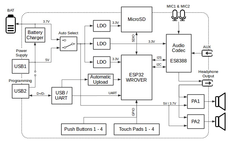
ESP32-LyraT V4.3 Electrical Block Diagram
Functional Description
The following list and figure describe key components, interfaces and controls of the ESP32-LyraT board.
- ESP32-WROVER Module
- The ESP32-WROVER module contains ESP32 chip to provide Wi-Fi / BT connectivity and data processing power as well as integrates 32 Mbit SPI flash and 32 Mbit PSRAM for flexible data storage.
- Green LED
- A general purpose LED controlled by the ESP32-WROVER Module to indicate certain operation states of the audio application using dedicated API.
- Function DIP Switch
- Used to configure function of GPIO12 to GPIO15 pins that are shared between devices, primarily between JTAG Header and MicroSD Card. By default, the MicroSD Card is enabled with all switches in OFF position. To enable the JTAG Header instead, switches in positions 3, 4, 5 and 6 should be put ON. If JTAG is not used and MicroSD Card is operated in the one-line mode, then GPIO12 and GPIO13 may be assigned to other functions. Please refer to ESP32 LyraT V4.3 schematic for more details.
- JTAG Header
- Provides access to the JTAG interface of ESP32-WROVER Module. It may be used for debugging, application upload, as well as implementing several other functions, e.g., Application Level Tracing. See JTAG Header / JP7 for pinout details. Before using JTAG signals to the header, Function DIP Switch should be enabled. Please note that when JTAG is in operation, MicroSD Card cannot be used and should be disconnected because some of JTAG signals are shared by both devices.
- UART Header
- Serial port: provides access to the serial TX/RX signals between ESP32-WROVER Module and USB-UART Bridge Chip.
- I2C Header
- Provides access to the I2C interface. Both ESP32-WROVER Module and Audio Codec Chip are connected to this interface. See I2C Header / JP5 for pinout details.
- MicroSD Slot
- The development board supports a MicroSD card in SPI/1-bit/4-bit modes, and can store or play audio files in the MicroSD card. Note that JTAG cannot be used and should be disconnected by setting Function DIP Switch when MicroSD Card is in operation, because some of signals are shared by both devices.
- I2S Header
- Provides access to the I2S interface. Both ESP32-WROVER Module and Audio Codec Chip are connected to this interface. See I2S Header / JP4 for pinout details.
- Left Microphone
- Onboard microphone connected to IN1 of the Audio Codec Chip.
- AUX Input
- Auxiliary input socket connected to IN2 (left and right channel) of the Audio Codec Chip. Use a 3.5 mm stereo jack to connect to this socket.
- Headphone Output
Output socket to connect headphones with a 3.5 mm stereo jack.
Note
The socket may be used with mobile phone headsets and is compatible with OMPT standard headsets only. It does work with CTIA headsets. Please refer to Phone connector (audio) on Wikipedia.
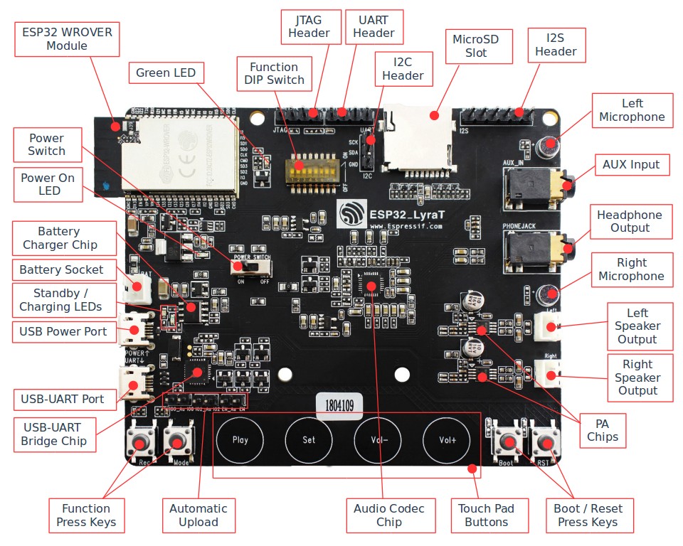
ESP32-LyraT V4.3 Board Layout
- Right Microphone
- Onboard microphone connected to IN1 of the Audio Codec Chip.
- Left Speaker Output
- Output socket to connect 4 ohm speaker. The pins have a standard 2.54 mm / 0.1” pitch.
- Right Speaker Output
- Output socket to connect 4 ohm speaker. The pins have a standard 2.54 mm / 0.1” pitch.
- PA Chip
- A power amplifier used to amplify stereo audio signal from the Audio Codec Chip for driving two 4-ohm speakers.
- Boot/Reset Press Keys
- Boot button: holding down the Boot button and momentarily pressing the Reset button to initiate the firmware download mode. Then you can download firmware through the serial port. Reset button: pressing this button alone resets the system.
- Touch Pad Buttons
- Four touch pads labeled Play, Sel, Vol+ and Vol-. They are routed to ESP32-WROVER Module and intended for development and testing of a UI for audio applications using dedicated API.
- Audio Codec Chip
- The Audio Codec Chip, ES8388, is a low power stereo audio codec with a headphone amplifier. It consists of 2-channel ADC, 2-channel DAC, microphone amplifier, headphone amplifier, digital sound effects, analog mixing and gain functions. It is interfaced with ESP32-WROVER Module over I2S and I2S buses to provide audio processing in hardware independently from the audio application.
- Automatic Upload
- Install three jumpers on this header to enable automatic loading of application to the ESP32. Install all jumpers together on all three headers. Remove all jumpers after upload is complete.
- Function Press Keys
- Two key labeled Rec and Mode. They are routed to ESP32-WROVER Module and intended for developing and testing a UI for audio applications using dedicated API.
- USB-UART Bridge Chip
- A single chip USB-UART bridge provides up to 1 Mbps transfers rate.
- USB-UART Port
- Functions as the communication interface between a PC and the ESP32 module.
- USB Power Port
- Provides the power supply for the board.
- Standby / Charging LEDs
- The Standby green LED indicates that power has been applied to the Micro USB Port. The Charging red LED indicates that a battery connected to the Battery Socket is being charged.
- Battery Socket
Two pins socket to connect a single cell Li-ion battery.
Note
Please verify if polarity on the battery plug matches polarity of the socket as marked on the board’s soldermask besides the socket.
- Battery Charger Chip
- Constant current & constant voltage linear charger for single cell lithium-ion batteries AP5056. Used for charging of a battery connected to the Battery Socket over the Micro USB Port.
- Power On LED
Red LED indicating that Power On Switch is turned on.
Note
The Power On Switch does not affect / disconnect the Li-ion battery charging.
- Power Switch
- Power on/off knob: toggling it to the left powers the board on; toggling it to the right powers the board off.
Hardware Setup Options
There are a couple of options to change the hardware configuration of the ESP32-LyraT board. The options are selectable with the Function DIP Switch.
Enable MicroSD Card in 1-wire Mode
| DIP SW | Position |
|---|---|
| 1 | OFF |
| 2 | OFF |
| 3 | OFF |
| 4 | OFF |
| 5 | OFF |
| 6 | OFF |
| 7 | OFF 1 |
| 8 | n/a |
- AUX Input detection may be enabled by toggling the DIP SW 7 ON. Note that the AUX Input signal pin should not be be plugged in when the system powers up. Otherwise the ESP32 may not be able to boot correctly.
In this mode:
- JTAG functionality is not available
- Vol- touch button is available for use with the API
Enable MicroSD Card in 4-wire Mode
| DIP SW | Position |
|---|---|
| 1 | ON |
| 2 | ON |
| 3 | OFF |
| 4 | OFF |
| 5 | OFF |
| 6 | OFF |
| 7 | OFF |
| 8 | n/a |
In this mode:
- JTAG functionality is not available
- Vol- touch button is not available for use with the API
- AUX Input detection from the API is not available
Enable JTAG
| DIP SW | Position |
|---|---|
| 1 | OFF |
| 2 | OFF |
| 3 | ON |
| 4 | ON |
| 5 | ON |
| 6 | ON |
| 7 | ON |
| 8 | n/a |
In this mode:
- MicroSD Card functionality is not available, remove the card from the slot
- Vol- touch button is not available for use with the API
- AUX Input detection from the API is not available
Using Automatic Upload
Entering of the ESP32 into upload mode may be done in two ways:
- Manually by pressing both Boot and RST keys and then releasing first RST and then Boot key.
- Automatically by software performing the upload. The software is using DTR and RTS signals of the serial interface to control states of EN, IO0 and IO2 pins of the ESP32. This functionality is enabled by installing jumpers in three headers JP23, JP24 and JP25. For details see ESP32 LyraT V4.3 schematic. Remove all jumpers after upload is complete.
Allocation of ESP32 Pins
Several pins ESP32 module are allocated to the on board hardware. Some of them, like GPIO0 or GPIO2, have multiple functions. Please refer to the table below or ESP32 LyraT V4.3 schematic for specific details.
| GPIO Pin | Type | Function Definition |
|---|---|---|
| SENSOR_VP | I | Audio Rec (PB) |
| SENSOR_VN | I | Audio Mode (PB) |
| IO32 | I/O | Audio Set (TP) |
| IO33 | I/O | Audio Play (TP) |
| IO27 | I/O | Audio Vol+ (TP) |
| IO13 | I/O | JTAG MTCK, MicroSD D3, Audio Vol- (TP) |
| IO14 | I/O | JTAG MTMS, MicroSD CLK |
| IO12 | I/O | JTAG MTDI, MicroSD D2, Aux signal detect |
| IO15 | I/O | JTAG MTDO, MicroSD CMD |
| IO2 | I/O | Automatic Upload, MicroSD D0 |
| IO4 | I/O | MicroSD D1 |
| IO34 | I | MicroSD insert detect |
| IO0 | I/O | Automatic Upload, I2S MCLK |
| IO5 | I/O | I2S SCLK |
| IO25 | I/O | I2S LRCK |
| IO26 | I/O | I2S DSDIN |
| IO35 | I | I2S ASDOUT |
| IO19 | I/O | Headphone jack insert detect |
| IO22 | I/O | Green LED indicator |
| IO21 | I/O | PA Enable output |
| IO18 | I/O | I2C SDA |
| IO23 | I/O | I2C SCL |
- (TP) - touch pad
- (PB) - push button
Pinout of Extension Headers
There are several pin headers available to connect external components, check the state of particular signal bus or debug operation of ESP32. Note that some signals are shared, see section Allocation of ESP32 Pins for details.
UART Header / JP2
| Header Pin | |
|---|---|
| 1 | 3.3V |
| 2 | TX |
| 3 | RX |
| 4 | GND |
I2S Header / JP4
| I2C Header Pin | ESP32 Pin | |
|---|---|---|
| 1 | MCLK | GPI0 |
| 2 | SCLK | GPIO5 |
| 1 | LRCK | GPIO25 |
| 2 | DSDIN | GPIO26 |
| 3 | ASDOUT | GPIO35 |
| 3 | GND | GND |
I2C Header / JP5
| I2C Header Pin | ESP32 Pin | |
|---|---|---|
| 1 | SCL | GPIO23 |
| 2 | SDA | GPIO18 |
| 3 | GND | GND |
JTAG Header / JP7
| ESP32 Pin | JTAG Signal | |
|---|---|---|
| 1 | MTDO / GPIO15 | TDO |
| 2 | MTCK / GPIO13 | TCK |
| 3 | MTDI / GPIO12 | TDI |
| 4 | MTMS / GPIO14 | TMS |
Notes of Power Distribution
The board features quite extensive power distribution system. It provides independent power supplies to all critical components. This should reduce noise in the audio signal from digital components and improve overall performance of the components.
Power Supply Separation
The main power supply is 5V and provided by a USB. The secondary power supply is 3.7V and provided by an optional battery. The USB power itself is fed with a dedicated cable, separate from a USB cable used for an application upload. To further reduce noise from the USB, the battery may be used instead of the USB.
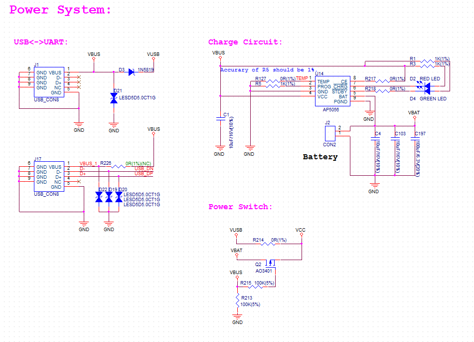
ESP32 LyraT V4.3 - Power Supply Separation
Three Dedicated LDOs
ESP32 Module
To provide enough current the ESP32, the development board adopts LD1117S33CTR LDO capable to supply the maximum output current of 800mA.
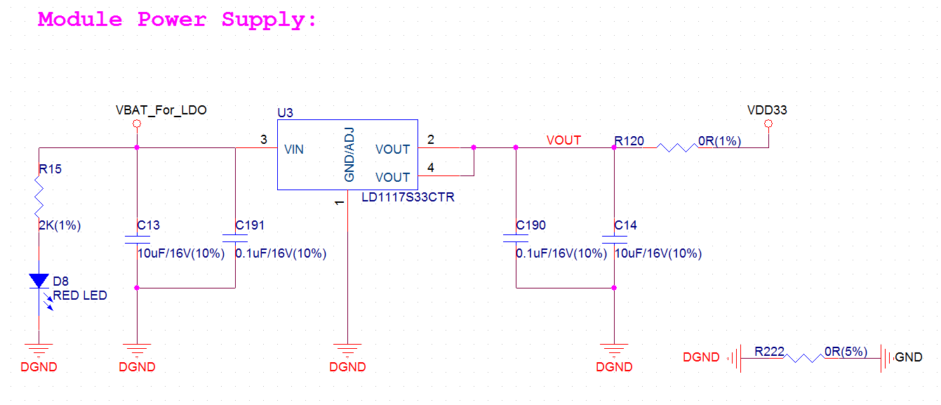
ESP32 LyraT V4.3 - Dedicated LDO for the ESP32 Module
MicroSD Card and Audio Codec
Two separate LDOs are provided for the MicorSD Card and the Audio Codec. Both circuits have similar design that includes an inductor and double decoupling capacitors on both the input and output of the LDO.
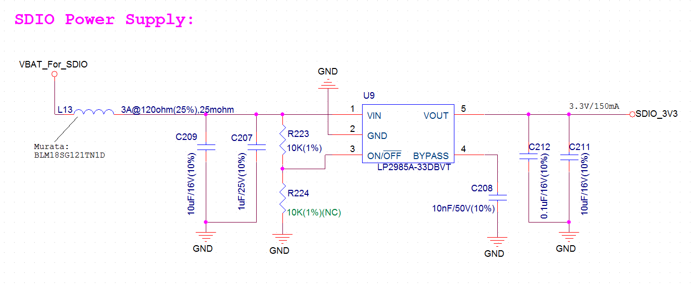
ESP32 LyraT V4.3 - Dedicated LDO for the MicroSD Card
Separate Power Feed for the PAs
The audio amplifier unit features two NS4150 that require a large power supply for driving external speakers with the maximum output power of 3W. The power is supplied directly to both PAs from the battery or the USB. The development board adds a set of LC circuits at the front of the PA power supply, where L uses 1.5A magnetic beads and C uses 10uF aluminum electrolytic capacitors, to effectively filter out power crosstalk.
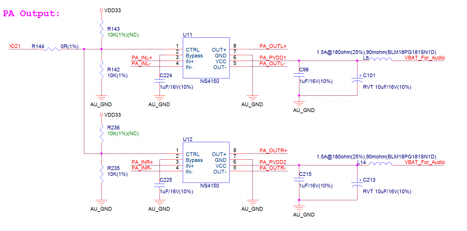
ESP32 LyraT V4.3 - Power Supply for the PAs
Selecting of the Audio Output
The development board uses two mono Class D amplifier ICs, model number NS4150 with maximum output power of 3W and operating voltage from 3.0V to 5.25V.
The audio input source is the digital-to-analog converter (DAC) output of the ES8388. Audio output supports two external speakers.
An optional audio output is a pair of headphones feed from the same DACs as the amplifier ICs.
To switch between using headphones and speakers, the board provides a digital input signal to detect when a headphone jack is inserted and a digital output signal to enable or disable the amplifier ICs. In other words selection between speakers and headphones is under software control instead of using mechanical contacts that would disconnect speakers once a headphone jack is inserted.